Linear 10
This project started as a simple idea while browsing through the LT3080 datasheet. I came across a lab supply schematic that immediately caught my attention. The concept is simple: take the original schematic and add some more functionality, make a simple instrument that is convenient to use.
In the end, this project proved to be a far more complex and rewarding challenge than I initially anticipated. Navigating these obstacles provided an incredible learning curve, reshaping my entire approach to the field. If I were to highlight the single most important takeaway, it would be the impact of noise—specifically, how it affects both our circuits and the surrounding environment. I am already planning ‘Version 2,’ where I’ll apply these insights to build a refined solution from a completely fresh perspective.
The Schematic
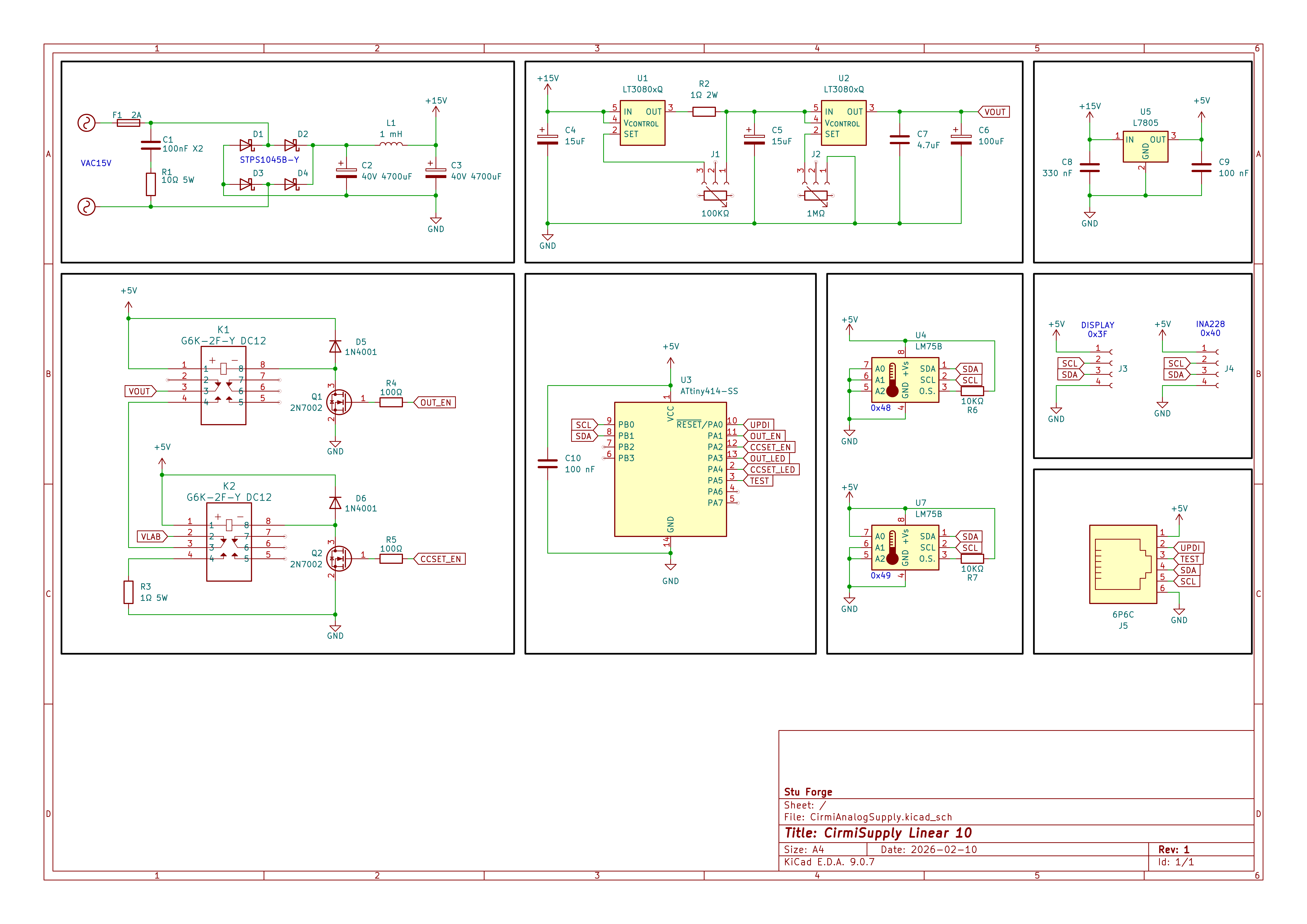 The schematic of the supply.
Voltage & Current regulation
As I mentioned, the heart of the system is the Analog Devices LT3080 low dropout linear regulator, two of them: one for voltage, and the other for current regulation.
It’s built around a simple but unusual principle: instead of using a fixed internal voltage reference, it uses a precise constant current source (~10 µA) on its SET pin. By placing a resistor between SET and ground, this current creates a voltage (V = I × R), and the regulator then forces its output voltage to match the SET pin voltage. In other words, the output voltage is directly defined by the resistor connected to the SET pin.
For voltage regulation, this makes the device extremely flexible. The output voltage is simply Vout = 10 µA × Rset, allowing easy adjustment over a wide range with a single resistor or potentiometer.
For current regulation, the device leverages the same principle in a clever way. A sense resistor is placed in series with the load, and the SET pin is referenced to the lower side of this resistor instead of ground. The regulator then adjusts its output so that the voltage across the sense resistor equals the voltage generated at the SET pin. Since the voltage across the sense resistor is proportional to current (V = I × R), this effectively creates a constant current source. The resulting current is given by I = (10 µA × Rset) / Rsense.
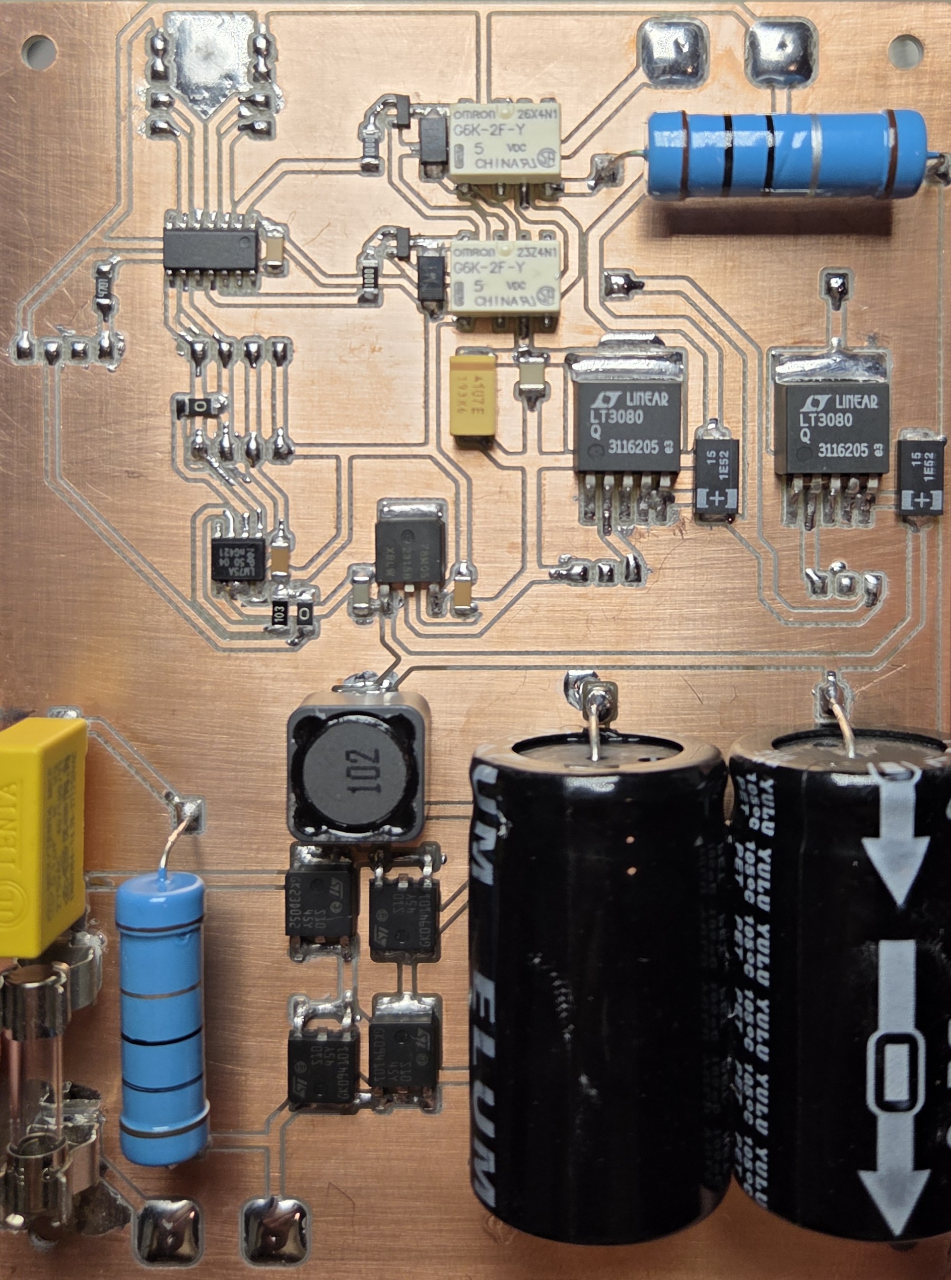 The main PCB of the supply.
In this configuration, the output voltage is not fixed; it automatically adjusts to whatever level is required to maintain the set current through the load. This allows the LT3080 to operate seamlessly as either a voltage regulator or a constant current source, depending on the external configuration.
For a deeper and more detailed explanation, the IC’s datasheet provides a comprehensive breakdown of its operation and application circuits.
Output stage
To measure the output voltage and current, I used the INA228. I decided to write a custom interface for the IC, as including both the Wire and LiquidCrystal_I2C libraries left limited flash and memory available. It seemed more practical to implement communication with the INA228 than to develop a 1602 display driver library from scratch. I took the same approach with the LM75 as well – in both cases I used Wire to transmit to the I2C bus.
2 relays, one for switching the output, another for shorting the output through a resistor, making it easy to set the current limit.
MCU and Display
My love for the ATtiny series continues—I picked the ATtiny414 as the brain of this project, and honestly, I just really enjoy working with these chips. They’ve got plenty of useful peripherals and capabilities, come in an easy-to-solder SOIC package, and best of all, they don’t require any external components to run. (Well, apart from the usual decoupling capacitor between VCC and GND, which is always a good idea.)
So far, I’ve only programmed them using the Arduino IDE, but it’s been working perfectly fine for my needs. I’m definitely planning to keep using these wherever I can.
Initially, I considered using an ST7567S display, but given the limited MCU resources and the physical space on the front panel, I decided to go with the 1602. Sorry ST7567S, see you next time - maybe with a custom driver library, just like I did with the 48x88 OLED displays.
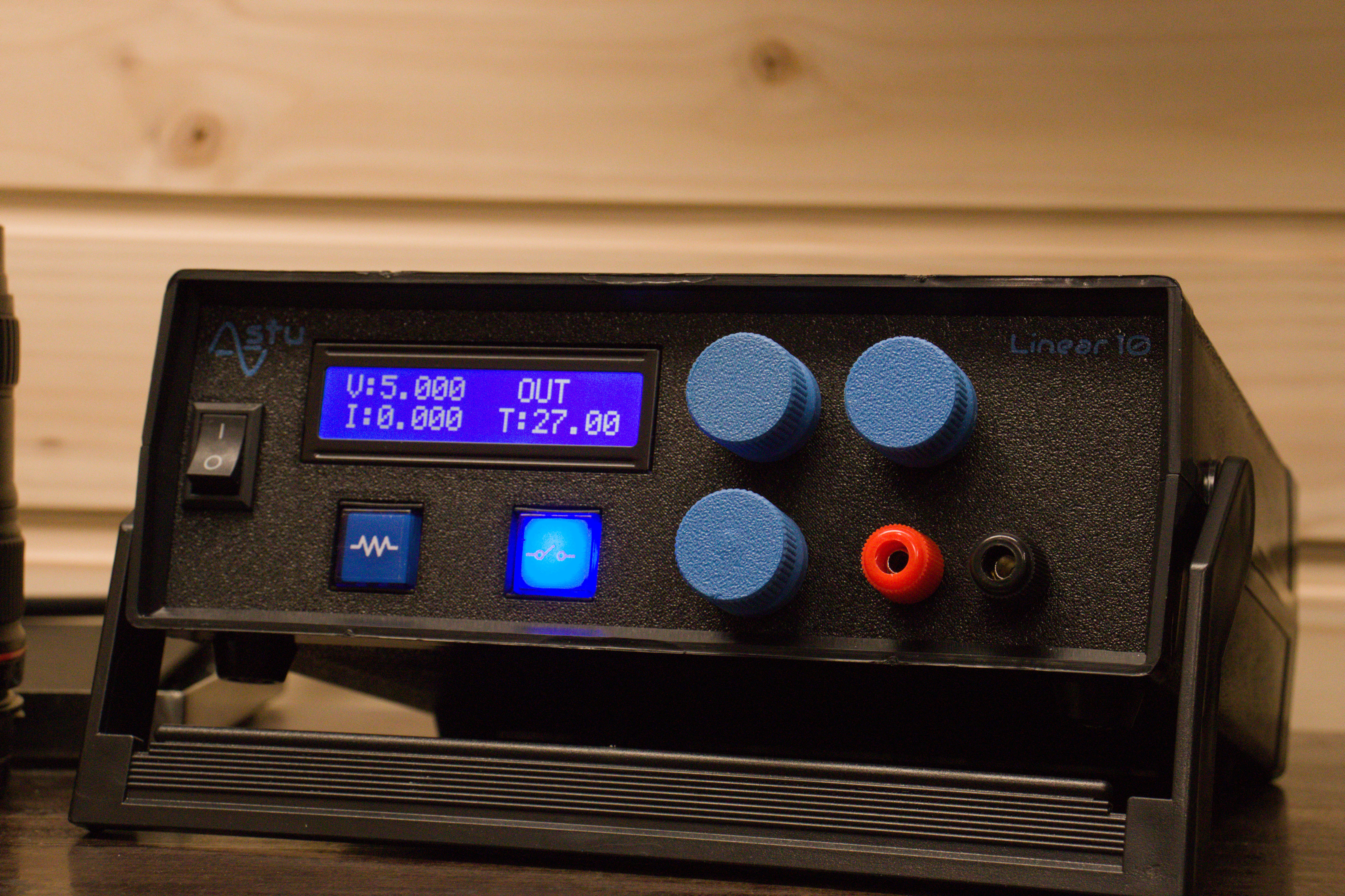
Buttons
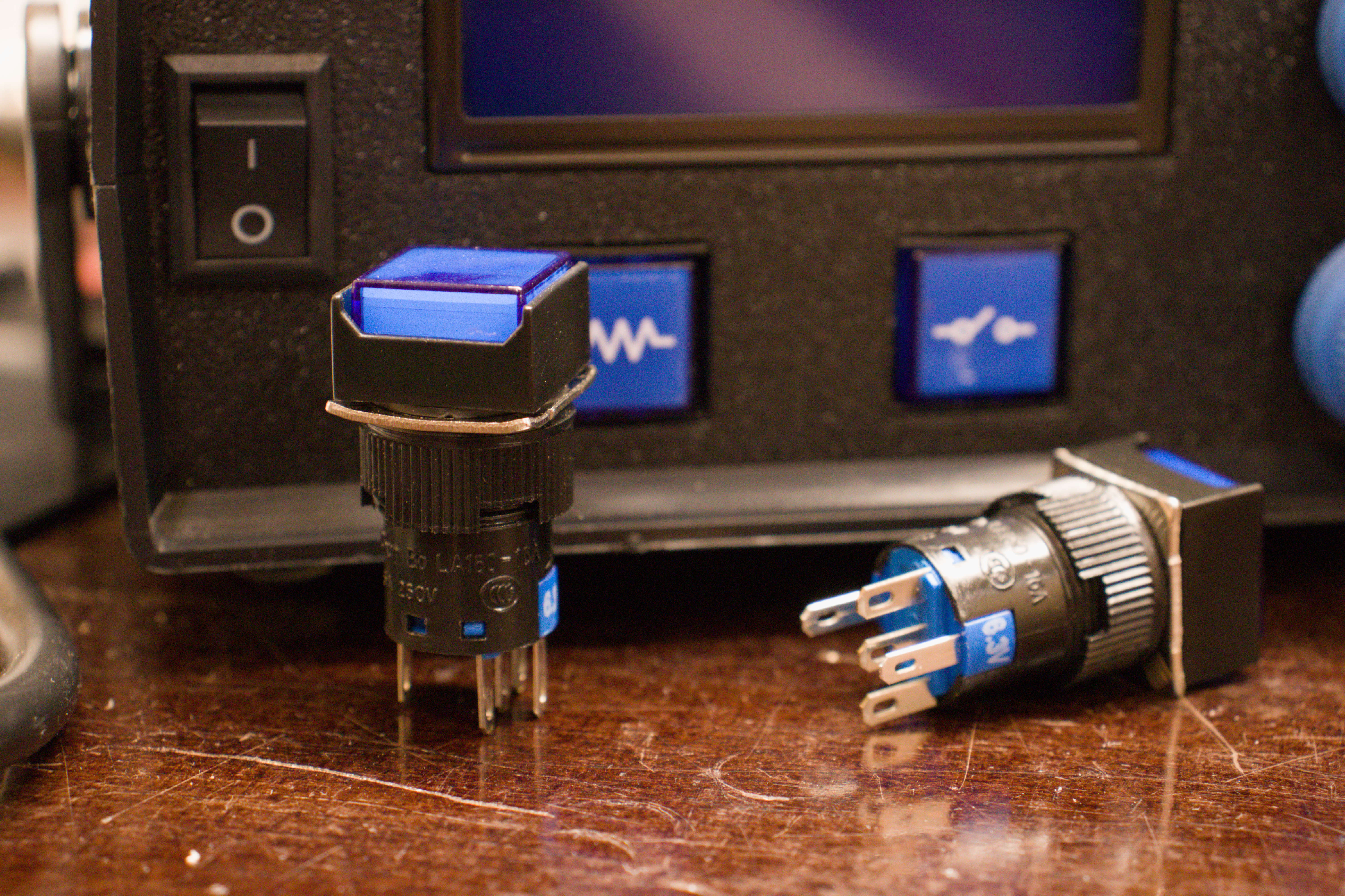 If you think about human–machine interaction, one of the simplest and most common methods is the use of buttons. In my vision, I always strive to create the best possible interaction between humans and machines, and one of the most important aspects of this is the feel. How it feels to press a button, the force required to activate it, the sensation when it clicks, and even the sound it produces. The buttons I used here have a particularly satisfying feel, making them a real joy to use.